Split-flow NFT for Marchantia
Experiments with different propagation techniques for Marchantia polymorpha strongly indicated that nutrient film technique (NFT) hydroponics could produce rapidly growing plants, and avoid some of the difficulties associated with solid media. However, most hydroponic culture systems rely on different ways of providing nutrient directly to the plant root system. Plants are generally supported by some sort of collar, and the nutrient and roots are shielded from light to avoid algal overgrowth. Marchantia, like other bryophytes, does not have a root system, instead it produces single-cell rhizoids from the lower surface of its flat thallus, and grows outwards, not upwards. Marchantia tissues can be cast over the surface of a medium, will germinate/regenerate with very high efficiency, and are capable of high rates of growth. Unfortunately, cultures grown in the open will be rapidly colonised by algae and other microbes.

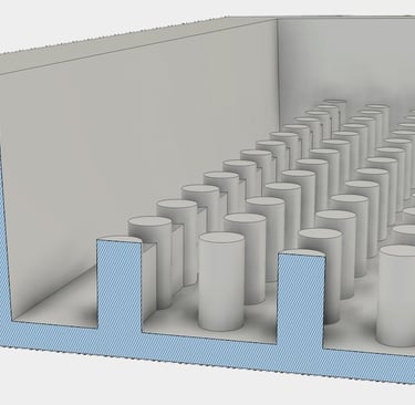
The development of efficient hydroponic systems for Marchantia has required tackling two main challenges: (i) how to to produce a growing surface that will provide water and nutrient to gemmae or thalli that have been transferred to the surface, while avoiding access of algae to the same exposed nutrient, and (ii) how to provide a sub-compartment that allows growth and feeding of rhizoids, but suppresses algae by excluding light. This is analogous to the covered tubes or trays that contain root systems in conventional NFT approaches.
My current approach is to print custom trays for nutrient film technique (NFT) hydroponics where the flow of recycled nutrient is split into two separate flows. Nutrient is pumped into a small reservoir of nutrient at the top of an NFT tray - formed behind a dam wall printed on the tray. First: this reservoir feeds a capillary mat draws and siphons nutrient down through the top growing surface of the tray, eventually dripping into the outlet ports. Second, the dam is set with spillways that allow media to flow onto the the lower surface of the tray and to flow as a film between the support pegs, down to the outlet ports. These lower compartments promote prolific growth of rhizoids as they emerge from the upper growing surface.
In the 'Technique' section of this website, I describe some of the observations that informed the current design: the testing different membrane surfaces and use of support pegs to create a subsurface chamber for rhizoid growth and feeding. I'll use "Split-flow NFT" as shorthand term to distinguish this approach from standard NFT.
First, I tested the delivery of nutrient solution to trays that had a dam around the inlet port(s), and looked for even delivery of liquid across the tray. Videos of a suitable tray are shown below - showing flow from the inlet dam onto the tray, and exit as the nutrient solution flows to the outlet ports. The tray was printed with a 4% downwards slope. I normally use generic Black PLA filaments for the tray prints. Some filaments produce a surface that is initially hydrophobic and flows across the surface that can bead, and not spread evenly over the surface. Curious, I tried spraying the trays with commercial Anti-fog products (Motoverde Fog-Away and Rain-X Anti-Fog - used to reduce condensation on car windows). These were both effective at reducing beading on the tray surface. However, running the trays for a day or two without other treatment also produced even-flowing films - either by washing the surface and/or forming some surface layer. Either way, this doesn't seem to eb a problem with PLA printed trays, and also easy to check.
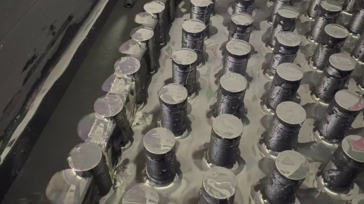
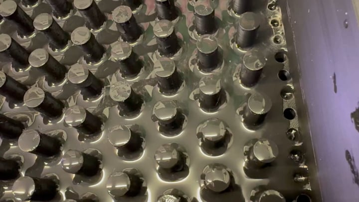
Inlet: Flow of nutrient solution into a tray, filling the inlet dam and flowing over the lip and down onto the lower surface of the inclined tray. The 20mm support pegs elevate the growing surface over the trays and create an excellent space for rhizoid growth.
Outlet: Flow through to the lower part of the tray, where there is a line of outlet ports that allow the nutrient media to drip back into the lower reservoir vessel. The staged drop of nutrient likely helps with oxygenation of the recycled media.


Growing surface
The choice of growing surface was based on early experiments which suggested the use of a triple layer of (i) plastic support mesh over the support pegs, (ii) Henofa 300 capillary matting that is dipped into the inlet reservoir and (iii) the surface-attached Henofa BF micro perforated plastic film. The three layers are shown below with a generalised diagram of a Split-flow NFT tray. The membranes are shown in schematic form and not to scale. Nutrient is pumped into the reservoir (left hand side), which then contributes to wetting of the capillary mat and flow under the growing surface, and spillover on to the lower surface of the tray. White arrows show the split paths for flow of the nutrient solution.


Split growth: thallus and rhizoid proliferation
Trials with the split-flow NFT confirmed that both thallus and rhizoid growth was prolific under these conditions. It should be noted that the the deeper support pegs were required for good rhizoid accumulation. 2cm deep pegs performed best, while 0.5cm and 1.0cm deep pegs should be avoided. Note also that the relative rate of nutrient delivery by pump might affect these observations. Under the conditions that I have used (with the materials described in following pages), the sub-surface flow of media is enough to fully wet the surface of the tray, but not enough to fill and water log the chambers. I have also tested the addition of an air pump and airstone to oxygenate the media in the main reservoir - but this made little impact on plant growth.
Building grow-pods
The following pages provide instructions for building practical split-flow NFT hydroponic vessels of different sizes. They all follow the general tray design that is outlined on this page, and each consists of a stacked arrangement of:
LED light system
Propagator cover or shield
Spilt-NFT tray
Nutrient tank and submersible pump
Custom 3D printing is used to adapt the different components. As the designs are relatively new, there will be plenty of room for improvements or adaptation to local components, which is where the flexibility of 3D printing is helpful. Possible modifications include addition of environmental sensors, gas-tight lids for CO2 supplementation, etc.
Marchantia as a platform for engineering plants
About Biomaker OpenPlant Cambridge Lab
Jim Haseloff
jimhaseloff@gmail.com

